FANUC ROBOCUT C600iC: 3D Coordinate Rotation
The FANUC ROBOCUT‘s 3D Coordinate System Rotation function compensates the wire vertical position by moving the U/V axes relative to the workpiece tilt. In this video, Bill Burba — Methods’ Technical Product Director for FANUC ROBOCUT — demonstrates how to 3D Coordinate Rotation on the ROBOCUT C600iC without a probe or indicator to measure a plate to see if it’s flat or adjust the wire to the plate.
1. What is the use case for 3D Coordinate Rotation?
This function allows production parts to be loaded and unloaded into a wire machine without having to confirm that the parts are indicated on the top surface, and adjust in fixture to be parallel to the table surface.
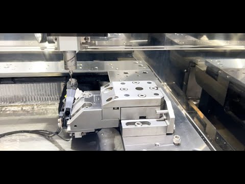
In this example, Bill demonstrates that a part that cannot be held “squarely” due to casting draft angles. He still picked up a bore at an inclined angle, and machined without having to indicate the two bores in and without keeping the wire straight.
The wire will cut at a compound angle and keep the surface it is cutting perpendicular to the surface it measured.
2. Why and when would an operator use this method versus probing and/or other standard procedures?
Standard methods require the operator probe to indicate the part while it is on the table. If the part (in the fixture) is not parallel to the table, adjustments need to be made. The demo above is a time saving approach. While the machine uses the probe to verify or setup the coordinate system rotation, the casting can be used to locate the edge of the part and to align a crooked part up for machining. The above method saves time and prevents consumable use, but not leveraging the wire to do the pickups.